HVAC Heat Load Calculation Excel Spreadsheet (Manual J Block Load, BTU/hr & Tonnage Sizing Calculator)
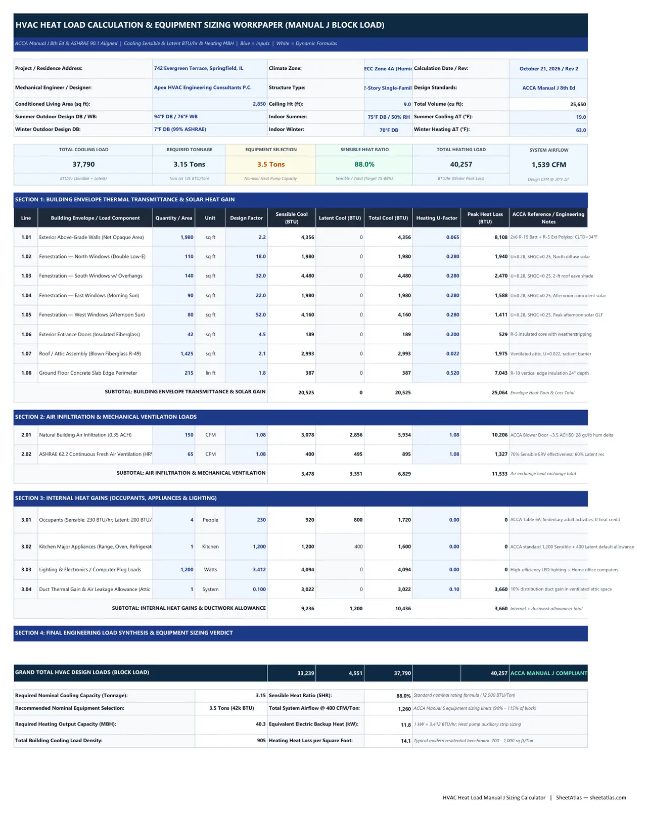
01_HVAC_Block_Load_Summary — Interactive Spreadsheet
| # | A | B | C | D | E | F | G | H | I | J | K |
|---|---|---|---|---|---|---|---|---|---|---|---|
| 1 | HVAC HEAT LOAD CALCULATION & EQUIPMENT SIZING WORKPAPER (MANUAL J BLOCK LOAD) | ||||||||||
| 2 | ACCA Manual J 8th Ed & ASHRAE 90.1 Aligned | Cooling Sensible & Latent BTU/hr & Heating MBH | Blue = Inputs | White = Dynamic Formulas | ||||||||||
| 3 | |||||||||||
| 4 | Project / Residence Address: | 742 Evergreen Terrace, Springfield, IL | Climate Zone: | IECC Zone 4A (Humid) | Calculation Date / Rev: | October 21, 2026 / Rev 2 | |||||
| 5 | Mechanical Engineer / Designer: | Apex HVAC Engineering Consultants P.C. | Structure Type: | 2-Story Single-Family | Design Standards: | ACCA Manual J 8th Ed | |||||
| 6 | Conditioned Living Area (sq ft): | Ceiling Ht (ft): | Total Volume (cu ft): | 25,650 | |||||||
| 7 | Summer Outdoor Design DB / WB: | 94°F DB / 76°F WB | Indoor Summer: | 75°F DB / 50% RH | Summer Cooling ΔT (°F): | ||||||
| 8 | Winter Outdoor Design DB: | 7°F DB (99% ASHRAE) | Indoor Winter: | 70°F DB | Winter Heating ΔT (°F): | ||||||
| 9 | |||||||||||
| 10 | TOTAL COOLING LOAD | REQUIRED TONNAGE | EQUIPMENT SELECTION | SENSIBLE HEAT RATIO | TOTAL HEATING LOAD | SYSTEM AIRFLOW | |||||
| 11 | 37,790 | 3.15 Tons | 3.5 Tons | 88.0% | 40,257 | 1,539 CFM | |||||
| 12 | BTU/hr (Sensible + Latent) | Tons (at 12k BTU/Ton) | Nominal Heat Pump Capacity | Sensible / Total (Target 75-88%) | BTU/hr (Winter Peak Loss) | Design CFM @ 20°F ΔT | |||||
| 13 | |||||||||||
| 14 | SECTION 1: BUILDING ENVELOPE THERMAL TRANSMITTANCE & SOLAR HEAT GAIN | ||||||||||
| 15 | Line | Building Envelope / Load Component | Quantity / Area | Unit | Design Factor | Sensible Cool (BTU) | Latent Cool (BTU) | Total Cool (BTU) | Heating U-Factor | Peak Heat Loss (BTU) | ACCA Reference / Engineering Notes |
| 16 | 1.01 | Exterior Above-Grade Walls (Net Opaque Area) | sq ft | 4,356 | 0 | 4,356 | 8,108 | 2x6 R-19 Batt + R-5 Ext Polyiso; CLTD=34°F | |||
| 17 | 1.02 | Fenestration — North Windows (Double Low-E) | sq ft | 1,980 | 0 | 1,980 | 1,940 | U=0.28, SHGC=0.25, North diffuse solar | |||
| 18 | 1.03 | Fenestration — South Windows w/ Overhangs | sq ft | 4,480 | 0 | 4,480 | 2,470 | U=0.28, SHGC=0.25, 2-ft roof eave shade | |||
| 19 | 1.04 | Fenestration — East Windows (Morning Sun) | sq ft | 1,980 | 0 | 1,980 | 1,588 | U=0.28, SHGC=0.25, Afternoon coincident solar | |||
| 20 | 1.05 | Fenestration — West Windows (Afternoon Sun) | sq ft | 4,160 | 0 | 4,160 | 1,411 | U=0.28, SHGC=0.25, Peak afternoon solar GLF | |||
| 21 | 1.06 | Exterior Entrance Doors (Insulated Fiberglass) | sq ft | 189 | 0 | 189 | 529 | R-5 insulated core with weatherstripping | |||
| 22 | 1.07 | Roof / Attic Assembly (Blown Fiberglass R-49) | sq ft | 2,993 | 0 | 2,993 | 1,975 | Ventilated attic, U=0.022, radiant barrier | |||
| 23 | 1.08 | Ground Floor Concrete Slab Edge Perimeter | lin ft | 387 | 0 | 387 | 7,043 | R-10 vertical edge insulation 24" depth | |||
| 24 | SUBTOTAL: BUILDING ENVELOPE TRANSMITTANCE & SOLAR GAIN | 20,525 | 0 | 20,525 | 25,064 | Envelope Heat Gain & Loss Total | |||||
| 25 | |||||||||||
| 26 | SECTION 2: AIR INFILTRATION & MECHANICAL VENTILATION LOADS | ||||||||||
| 27 | 2.01 | Natural Building Air Infiltration (0.35 ACH) | CFM | 3,078 | 2,856 | 5,934 | 10,206 | ACCA Blower Door ~3.5 ACH50; 28 gr/lb hum delta | |||
| 28 | 2.02 | ASHRAE 62.2 Continuous Fresh Air Ventilation (HRV/ERV) | CFM | 400 | 495 | 895 | 1,327 | 70% Sensible ERV effectiveness; 60% Latent rec | |||
| 29 | SUBTOTAL: AIR INFILTRATION & MECHANICAL VENTILATION | 3,478 | 3,351 | 6,829 | 11,533 | Air exchange heat exchange total | |||||
| 30 | |||||||||||
| 31 | SECTION 3: INTERNAL HEAT GAINS (OCCUPANTS, APPLIANCES & LIGHTING) | ||||||||||
| 32 | 3.01 | Occupants (Sensible: 230 BTU/hr; Latent: 200 BTU/hr) | People | 920 | 800 | 1,720 | 0 | ACCA Table 6A; Sedentary adult activities; 0 heat credit | |||
| 33 | 3.02 | Kitchen Major Appliances (Range, Oven, Refrigerator) | Kitchen | 1,200 | 400 | 1,600 | 0 | ACCA standard 1,200 Sensible + 400 Latent default allowance | |||
| 34 | 3.03 | Lighting & Electronics / Computer Plug Loads | Watts | 4,094 | 0 | 4,094 | 0 | High-efficiency LED lighting + Home office computers | |||
| 35 | 3.04 | Duct Thermal Gain & Air Leakage Allowance (Attic R-8) | System | 3,022 | 0 | 3,022 | 3,660 | 10% distribution duct gain in ventilated attic space | |||
| 36 | SUBTOTAL: INTERNAL HEAT GAINS & DUCTWORK ALLOWANCE | 9,236 | 1,200 | 10,436 | 3,660 | Internal + ductwork allowances total | |||||
| 37 | |||||||||||
| 38 | SECTION 4: FINAL ENGINEERING LOAD SYNTHESIS & EQUIPMENT SIZING VERDICT | ||||||||||
| 39 | |||||||||||
| 40 | |||||||||||
| 41 | |||||||||||
| 42 | GRAND TOTAL HVAC DESIGN LOADS (BLOCK LOAD) | 33,239 | 4,551 | 37,790 | 40,257 | ACCA MANUAL J COMPLIANT | |||||
| 43 | |||||||||||
| 44 | Required Nominal Cooling Capacity (Tonnage): | 3.15 | Sensible Heat Ratio (SHR): | 88.0% | Standard nominal rating formula (12,000 BTU/Ton) | ||||||
| 45 | Recommended Nominal Equipment Selection: | 3.5 Tons (42k BTU) | Total System Airflow @ 400 CFM/Ton: | 1,260 | ACCA Manual S equipment sizing limits (90% - 115% of block) | ||||||
| 46 | Required Heating Output Capacity (MBH): | 40.3 | Equivalent Electric Backup Heat (kW): | 11.8 | 1 kW = 3,412 BTU/hr; Heat pump auxiliary strip sizing | ||||||
| 47 | Total Building Cooling Load Density: | 905 | Heating Heat Loss per Square Foot: | 14.1 | Typical modern residential benchmark: 700 - 1,000 sq ft/Ton | ||||||
Free Instant Download
No email signup • Unlocked formulas
Built-In Excel Formulas & Calculation Logic
Unlocked native Microsoft Excel functions pre-programmed inside this workbook:
=ROUND(C16*E16, 0) Calculates heat gain through building envelope assemblies by multiplying the surface area (C16) by the design cooling load factor or U-factor multiplied by the cooling temperature difference (E16), conforming to ACCA Manual J conduction equations.
=ROUND(0.68*C27*28, 0) Computes latent moisture removal burden in BTU/hr by multiplying the psychrometric factor (0.68), volumetric infiltration or outdoor air intake rate in CFM (C27), and the outdoor-to-indoor humidity ratio delta in grains of moisture per pound of dry air (28 gr/lb).
=IFERROR(ROUND(F42/H42, 3), 0.85) Evaluates the proportion of sensible cooling capacity (F42) relative to total cooling capacity (H42). Maintaining an SHR between 0.75 and 0.88 guarantees adequate dehumidification performance and prevents humid, clammy indoor conditions in warm-weather climates.
=ROUND(H42/12000, 2) Converts total calculated peak cooling demand in BTU/hr (H42) into standard refrigeration tonnage by dividing by the fundamental engineering constant of 12,000 BTU/hr per ton of refrigeration (TR).
=ROUND((F42)/(1.08*20), 0) Determines total cubic feet per minute (CFM) of conditioned air required by dividing total sensible room heat gain (F42) by the standard air heat capacity constant (1.08) multiplied by the design supply-to-room temperature drop (20°F ΔT).
Full Workbook Print Layout Preview (.XLSX)
Overview & Industry Standard Alignment
Properly sizing heating, ventilation, and air conditioning (HVAC) systems is one of the most critical engineering responsibilities in residential and light commercial construction. For decades, contractors relied on inaccurate rules of thumb—such as allocating '500 square feet per ton'—which routinely resulted in severely oversized air conditioners and furnaces. Oversized cooling equipment cycles on and off rapidly, failing to run long enough to dehumidify the air, resulting in clammy indoor environments, elevated indoor humidity, biological mold growth, excessive electrical startup surges, and premature compressor burnout. Conversely, undersized equipment runs continuously on design days without satisfying the thermostat. This authoritative HVAC Heat Load Calculation Excel Workbook provides a rigorous, formula-driven engineering workpaper structured strictly according to the Air Conditioning Contractors of America (ACCA) Manual J 8th Edition and ASHRAE Fundamentals standards. The model eliminates guesswork by performing both an executive Whole-Building Block Load calculation and a detailed Room-by-Room Zonal Schedule. Every heat transfer mechanism is explicitly quantified: opaque wall and roof conduction, fenestration solar radiation via Glass Load Factors (GLF), foundation edge thermal loss, air infiltration via air changes per hour (ACH), mechanical ventilation recovery (HRV/ERV), and internal sensible and latent gains from occupants, kitchen appliances, and electronics. In addition to thermal load modeling, the workbook bridges the critical transition between heating/cooling loads and mechanical air distribution. Sheet 02 dynamically computes zone CFM requirements, while Sheet 03 executes an ACCA Manual D Equal Friction duct sizing schedule, verifying that duct velocities stay below 600–900 FPM to ensure whisper-quiet operation (NC-25/30). A complete External Static Pressure (ESP) budget worksheet balances duct friction against evaporator coils, high-efficiency MERV 11–13 media filters, and terminal grilles, ensuring your selected blower can deliver full rated airflow without exceeding its aerodynamic operating limits.
Practical Operational Use Cases:
New Residential Construction Permitting & Manual J/S Compliance
Generate clean, defensible Manual J load calculation reports and equipment sizing schedules required by municipal building departments, code officials, and Energy Star certification programs.
Heat Pump Electrification & Furnace/Boiler Replacement Sizing
Accurately establish real peak heat loss (MBH) and cooling tonnage when converting older homes from oversized fossil-fuel furnaces to modern inverter-driven cold-climate heat pumps.
Room-by-Room Airflow Balancing & Hot/Cold Room Remediation
Diagnose uneven temperatures across multi-level residences by comparing calculated room CFM requirements against existing branch duct capacities and register diffuser face sizes.
HVAC Ductwork Redesign & External Static Pressure (ESP) Budgeting
Calculate branch and trunk duct diameters using the equal friction method and verify that total system static pressure (including MERV 13 filters and wet cooling coils) stays within the blower fan curve limit.
Designed For:
What’s Inside the Workbook (Tab-by-Tab Breakdown)
Worksheet 1
Worksheet 2
Worksheet 3
Worksheet 4
Practitioner Tips & Best Practices
-
✓
Never size cooling equipment based on arbitrary square footage rules of thumb; modern energy-efficient homes typically require 700 to 1,000 sq ft per ton, meaning old rules will oversize systems by 30% to 60%.
-
✓
In humid climates (IECC Zones 1A, 2A, 3A, 4A), verify that the selected equipment Sensible Heat Ratio (SHR) matches your building load; if your sensible ratio is 0.78, an equipment SHR of 0.88 will fail to dehumidify properly.
-
✓
When computing fenestration loads, use coincident peak afternoon Glass Load Factors (GLF) rather than summing morning peak East solar gain with afternoon West solar gain, which would artificially inflate required block tonnage.
-
✓
Always account for pressure drop across high-MERV air filters; a 1-inch MERV 11 filter can impose 0.25 to 0.35 in. w.g. of restriction, leaving insufficient static pressure for ductwork on standard 0.50 in. w.g. blowers. Specify 4-inch or 5-inch deep media filter cabinets instead.
-
✓
If supply or return ductwork is routed through an unconditioned attic space, ensure the ducts are sealed to < 4% leakage and insulated to at least R-8, and add a 10% to 15% duct thermal gain allowance to the sensible cooling load.
Frequently Asked Questions
What is the difference between an ACCA Manual J 'Block Load' and a 'Room-by-Room Load'?
A 'Block Load' calculates the peak heating and cooling loads of the entire building as a single combined structure, accounting for coincident solar radiation (such as recognizing that the sun cannot shine on the east and west windows simultaneously). The block load is used to select the primary HVAC equipment capacity (tonnage and heating output under Manual S). In contrast, a 'Room-by-Room Load' calculates the individual peak load for each specific room at its worst-case hour, which is essential under Manual D to determine the exact cubic feet per minute (CFM) of airflow and duct sizes required for balanced temperature distribution.
Why is oversizing an air conditioner or heat pump harmful to home comfort and efficiency?
Oversized cooling equipment satisfies the thermostat setting very quickly and shuts off (short cycling). Because effective moisture removal (dehumidification) requires air to pass over a cold evaporator coil for at least 10 to 15 continuous minutes, short-cycling units cool the air without extracting sufficient water vapor. This creates a cold, clammy indoor environment with relative humidity exceeding 60%, fostering dust mites and mold growth. Furthermore, repeated short cycling causes severe mechanical stress on compressor motors, spikes electric utility bills due to frequent startup surges, and causes noisy airflow through undersized ductwork.
How does the Sensible Heat Ratio (SHR) affect air conditioning performance in humid climates?
Sensible Heat Ratio (SHR) is the ratio of sensible cooling load (lowering temperature) to total cooling load (sensible plus latent, where latent is moisture removal). In hot, arid climates like Phoenix, the SHR is typically 0.90 to 0.95 (almost purely sensible heat). In humid climates like Houston, Miami, or Atlanta, the SHR frequently drops to 0.75 to 0.82, meaning 20% to 25% of the cooling load is latent moisture removal. If you install an equipment package with a high factory SHR (e.g., 0.88) in a home with a 0.78 load SHR, the home will feel damp even when the temperature reads 72°F.
How do I calculate the required CFM airflow for individual rooms?
Room airflow is calculated using the sensible heat transfer formula: CFM = Room Sensible Heat Gain (BTU/hr) / (1.08 × ΔT), where 1.08 is the standard volumetric heat capacity constant of air at sea level (0.24 BTU/lb·°F × 0.075 lb/cu ft × 60 min/hr), and ΔT is the temperature difference between the room air (typically 75°F) and the supply air leaving the diffuser (typically 55°F, giving a 20°F ΔT). For a bedroom with 2,750 BTU/hr of sensible gain, CFM = 2,750 / (1.08 × 20) = 127 CFM. Our Sheet 02 automates this calculation for every room.
What is External Static Pressure (ESP) and why does Manual D enforce a maximum limit?
External Static Pressure (ESP) is the total resistance to airflow exerted on the HVAC system's blower fan, measured in inches of water column (in. w.g.). It encompasses the combined friction of the supply ductwork, return ductwork, evaporator cooling coil, air filter, dampers, and supply/return grilles. Standard residential residential blowers are typically rated to deliver design airflow against an ESP of 0.50 to 0.70 in. w.g. If restrictive ductwork, tight 90-degree elbows, or high-efficiency 1-inch filters push static pressure to 0.80 or 1.00 in. w.g., airflow drops dramatically, coils freeze into solid blocks of ice, electric heat strips overheat, and ECM variable-speed blower motors consume excessive power or fail prematurely.
How do modern low-E windows and continuous exterior insulation affect heating and cooling loads?
Modern building codes (such as IECC 2021) mandate high-performance thermal envelopes that drastically slash heating and cooling loads compared to older construction. Upgrading from single-pane clear glass (U=1.10, SHGC=0.75) to double-pane Low-E insulated glass (U=0.28, SHGC=0.25) reduces window solar gain by up to 66% and winter conductive heat loss by 75%. Adding R-5 continuous exterior rigid foam over 2x6 wood framing breaks thermal bridging across wall studs, cutting total wall heat transmission by nearly 30%. In a 2,850 sq ft home, these envelope upgrades can reduce required cooling capacity from 5.0 Tons down to 3.0 or 3.5 Tons, cutting equipment purchase costs and lifelong energy consumption.