NEC Voltage Drop & Copper/Aluminum Wire Sizing Calculator Excel Sheet (1-Phase & 3-Phase Feeder & Branch)
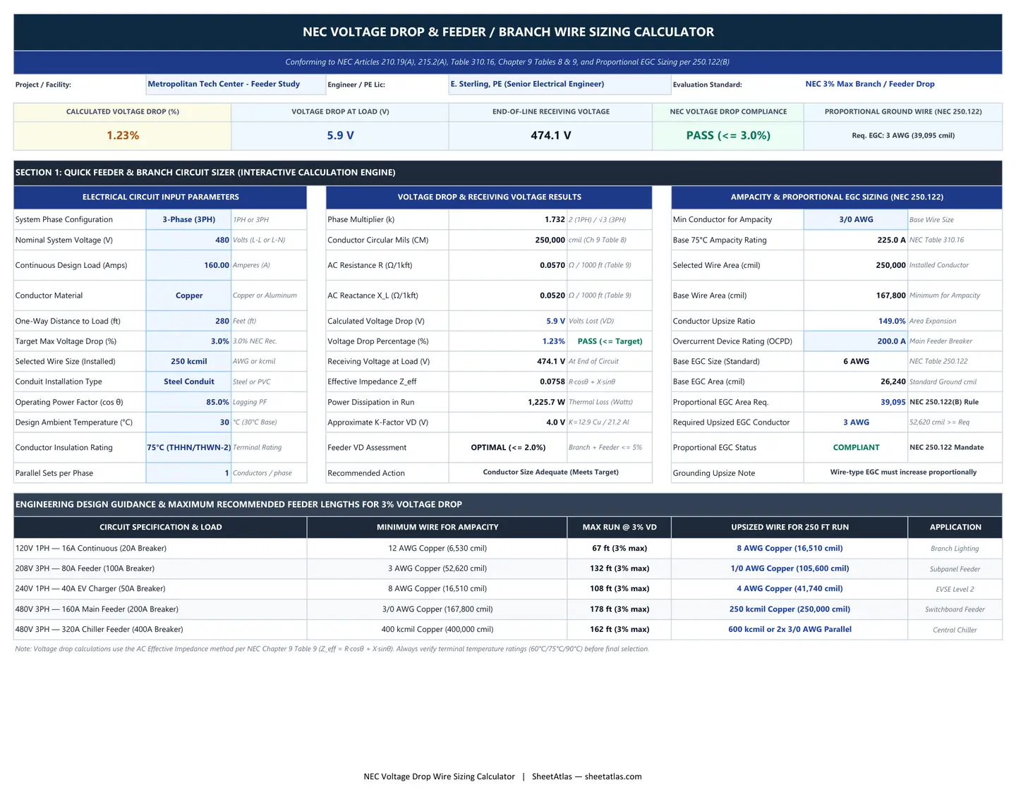
01_Quick_Feeder_Sizer — Interactive Spreadsheet
| # | A | B | C | D | E | F | G | H | I | J | K | L |
|---|---|---|---|---|---|---|---|---|---|---|---|---|
| 1 | NEC VOLTAGE DROP & FEEDER / BRANCH WIRE SIZING CALCULATOR | |||||||||||
| 2 | Conforming to NEC Articles 210.19(A), 215.2(A), Table 310.16, Chapter 9 Tables 8 & 9, and Proportional EGC Sizing per 250.122(B) | |||||||||||
| 3 | Project / Facility: | Metropolitan Tech Center - Feeder Study | Engineer / PE Lic: | E. Sterling, PE (Senior Electrical Engineer) | Evaluation Standard: | NEC 3% Max Branch / Feeder Drop | ||||||
| 4 | ||||||||||||
| 5 | CALCULATED VOLTAGE DROP (%) | VOLTAGE DROP AT LOAD (V) | END-OF-LINE RECEIVING VOLTAGE | NEC VOLTAGE DROP COMPLIANCE | PROPORTIONAL GROUND WIRE (NEC 250.122) | |||||||
| 6 | 1% | 5.9V | 474.1V | PASS (<= 3.0%) | Req. EGC: 3 AWG (39,095 cmil) | |||||||
| 7 | ||||||||||||
| 8 | SECTION 1: QUICK FEEDER & BRANCH CIRCUIT SIZER (INTERACTIVE CALCULATION ENGINE) | |||||||||||
| 9 | ELECTRICAL CIRCUIT INPUT PARAMETERS | VOLTAGE DROP & RECEIVING VOLTAGE RESULTS | AMPACITY & PROPORTIONAL EGC SIZING (NEC 250.122) | |||||||||
| 10 | System Phase Configuration | 3-Phase (3PH) | 1PH or 3PH | Phase Multiplier (k) | 1.73 | 2 (1PH) / √3 (3PH) | Min Conductor for Ampacity | 3/0 AWG | Base Wire Size | |||
| 11 | Nominal System Voltage (V) | Volts (L-L or L-N) | Conductor Circular Mils (CM) | 250,000 | cmil (Ch 9 Table 8) | Base 75°C Ampacity Rating | 225.0A | NEC Table 310.16 | ||||
| 12 | Continuous Design Load (Amps) | Amperes (A) | AC Resistance R (Ω/1kft) | 0.06 | Ω / 1000 ft (Table 9) | Selected Wire Area (cmil) | 250,000 | Installed Conductor | ||||
| 13 | Conductor Material | Copper | Copper or Aluminum | AC Reactance X_L (Ω/1kft) | 0.05 | Ω / 1000 ft (Table 9) | Base Wire Area (cmil) | 167,800 | Minimum for Ampacity | |||
| 14 | One-Way Distance to Load (ft) | Feet (ft) | Calculated Voltage Drop (V) | 5.9V | Volts Lost (VD) | Conductor Upsize Ratio | 149.0% | Area Expansion | ||||
| 15 | Target Max Voltage Drop (%) | 3.0% NEC Rec. | Voltage Drop Percentage (%) | 1% | PASS (<= Target) | Overcurrent Device Rating (OCPD) | Main Feeder Breaker | |||||
| 16 | Selected Wire Size (Installed) | 250 kcmil | AWG or kcmil | Receiving Voltage at Load (V) | 474.1V | At End of Circuit | Base EGC Size (Standard) | 6 AWG | NEC Table 250.122 | |||
| 17 | Conduit Installation Type | Steel Conduit | Steel or PVC | Effective Impedance Z_eff | 0.08 | R·cosθ + X·sinθ | Base EGC Area (cmil) | 26,240 | Standard Ground cmil | |||
| 18 | Operating Power Factor (cos θ) | Lagging PF | Power Dissipation in Run | 1,225.7W | Thermal Loss (Watts) | Proportional EGC Area Req. | 39,095 | NEC 250.122(B) Rule | ||||
| 19 | Design Ambient Temperature (°C) | °C (30°C Base) | Approximate K-Factor VD (V) | 4.0V | K=12.9 Cu / 21.2 Al | Required Upsized EGC Conductor | 3 AWG | 52,620 cmil >= Req | ||||
| 20 | Conductor Insulation Rating | 75°C (THHN/THWN-2) | Terminal Rating | Feeder VD Assessment | OPTIMAL (<= 2.0%) | Branch + Feeder <= 5% | Proportional EGC Status | COMPLIANT | NEC 250.122 Mandate | |||
| 21 | Parallel Sets per Phase | Conductors / phase | Recommended Action | Conductor Size Adequate (Meets Target) | Grounding Upsize Note | Wire-type EGC must increase proportionally | ||||||
| 22 | ||||||||||||
| 23 | ENGINEERING DESIGN GUIDANCE & MAXIMUM RECOMMENDED FEEDER LENGTHS FOR 3% VOLTAGE DROP | |||||||||||
| 24 | CIRCUIT SPECIFICATION & LOAD | MINIMUM WIRE FOR AMPACITY | MAX RUN @ 3% VD | UPSIZED WIRE FOR 250 FT RUN | APPLICATION | |||||||
| 25 | 120V 1PH — 16A Continuous (20A Breaker) | 12 AWG Copper (6,530 cmil) | 67 ft (3% max) | 8 AWG Copper (16,510 cmil) | Branch Lighting | |||||||
| 26 | 208V 3PH — 80A Feeder (100A Breaker) | 3 AWG Copper (52,620 cmil) | 132 ft (3% max) | 1/0 AWG Copper (105,600 cmil) | Subpanel Feeder | |||||||
| 27 | 240V 1PH — 40A EV Charger (50A Breaker) | 8 AWG Copper (16,510 cmil) | 108 ft (3% max) | 4 AWG Copper (41,740 cmil) | EVSE Level 2 | |||||||
| 28 | 480V 3PH — 160A Main Feeder (200A Breaker) | 3/0 AWG Copper (167,800 cmil) | 178 ft (3% max) | 250 kcmil Copper (250,000 cmil) | Switchboard Feeder | |||||||
| 29 | 480V 3PH — 320A Chiller Feeder (400A Breaker) | 400 kcmil Copper (400,000 cmil) | 162 ft (3% max) | 600 kcmil or 2x 3/0 AWG Parallel | Central Chiller | |||||||
| 30 | Note: Voltage drop calculations use the AC Effective Impedance method per NEC Chapter 9 Table 9 (Z_eff = R·cosθ + X·sinθ). Always verify terminal temperature ratings (60°C/75°C/90°C) before final selection. | |||||||||||
Free Instant Download
No email signup • Unlocked formulas
Built-In Excel Formulas & Calculation Logic
Unlocked native Microsoft Excel functions pre-programmed inside this workbook:
=ROUND((1.732 * G12 * (C12/C21) * (C14/1000) * (G12 * C18 + G13 * SQRT(1 - C18^2))), 2) Calculates three-phase line-to-line AC voltage drop using the National Electrical Code Chapter 9 Table 9 formula: VD = √3 · I · (L / 1,000) · (R·cosθ + X·sinθ), accounting for conductor resistance (R), inductive reactance (X), load power factor (cosθ), run distance, and parallel sets.
=ROUND((G14 / C11) * 100, 2) Evaluates percentage voltage drop against the nominal circuit voltage (C11) to verify strict adherence to NEC Article 210.19(A) Informational Note No. 4 (3.0% maximum recommended branch circuit drop) and NEC 215.2(A)(1) Informational Note No. 2 (5.0% maximum total feeder plus branch circuit drop).
=ROUND(C11 - G14, 1) Computes actual line voltage arriving at the load terminals under peak operating amperes. Ensures sensitive electronic ballasts, variable frequency drives (VFDs), and motor contactors do not experience under-voltage dropout or premature winding overheating.
=ROUNDUP(K17 * (K12 / K13), 0) Enforces NEC Article 250.122(B) compliance by multiplying standard Table 250.122 equipment grounding conductor (EGC) circular mil area (K17) by the ratio of installed phase conductor area (K12) to minimum ampacity conductor area (K13), ensuring sufficient fault-current clearing capacity.
Full Workbook Print Layout Preview (.XLSX)
Overview & Industry Standard Alignment
In commercial, industrial, and utility electrical installations, undersized conductors cause severe operational hazards including recurring circuit breaker nuisance trips, sluggish motor starting torque, flickering LED driver circuits, and permanent thermal insulation degradation. While standard electrical handbooks frequently rely on simplified DC resistance formulas (2·K·I·L / CM), AC circuits installed in metallic conduit experience significant inductive reactance (X_L) and skin effect that drastically increase total voltage drop—particularly on conductors 1/0 AWG and larger. This workbook provides electrical consulting engineers, master electricians, and MEP estimators with a rigorous, PE-validated calculation suite. By integrating Chapter 9 Table 9 AC effective impedance and Table 8 physical properties directly into dynamic lookup formulas, the spreadsheet computes both exact AC effective impedance (Z = R·cosθ + X·sinθ) and classical K-factor approximations. Users can instantly switch between copper and aluminum conductors, adjust load power factor (0.80 to 1.00), specify PVC versus rigid steel conduit, and evaluate parallel conductor configurations per phase. Crucially, this template addresses the most commonly cited code violation in commercial plan review: failure to up-size the equipment grounding conductor (EGC) under NEC Article 250.122(B). Whenever phase conductors are enlarged from their baseline ampacity size to mitigate voltage drop over long distances, the spreadsheet automatically calculates the exact required circular mil area for the ground wire, cross-references standard AWG gauges, and flags non-compliant installations before submittal to municipal inspection authorities.
Practical Operational Use Cases:
Commercial Central Chiller & Rooftop Unit (RTU) Feeder Engineering
Design 480V 3-phase feeders for central cooling plants located hundreds of feet from the main switchboard (MSB). Evaluate motor inrush and running current to verify that terminal voltage drop remains strictly below 2.0% on the feeder, ensuring proper VFD operation and compressor longevity.
Remote Municipal Wastewater Lift Station & Industrial Pump Stations
Size long utility service runs and pump branch circuits traversing 500 to 1,500 feet across plant facilities. Compare cost-benefit trade-offs between upsized copper vs. aluminum conductors and determine exact conduit fill and proportional ground conductor requirements.
Large Commercial Parking Lot & Highway High-Mast Lighting Branch Runs
Engineer 277V single-phase lighting branch circuits serving distributed poles across retail parking lots or logistics terminals. Calculate cumulative line-to-neutral voltage drop across distributed lighting loads to prevent LED luminaire driver brownout at distal fixture heads.
Utility-Scale Solar PV Inverter & Level 3 Commercial EV Charging Feeders
Size DC and 480V AC feeder interconnects for multi-megawatt commercial solar arrays and high-amperage DC Fast Chargers (DCFC). Calculate continuous thermal I²R losses to maximize energy harvest and minimize life-cycle operating costs.
Designed For:
What’s Inside the Workbook (Tab-by-Tab Breakdown)
Worksheet 1
Interactive single-circuit engineering calculator. Features high-level KPI summary cards, user input parameters (system voltage, phase, design amps, conductor material, one-way distance, power factor, conduit type, and parallel sets), real-time AC voltage drop and receiving voltage evaluation, and automated NEC 250.122(B) proportional equipment grounding conductor sizing.
Worksheet 2
Comprehensive 15-circuit engineering schedule for commercial and industrial facilities. Populated with realistic feeders (substations, chillers, cooling towers, lift stations, lighting panels, and subpanels) with active column formulas for nominal voltage, load amps, length, AC effective impedance, voltage drop in volts and percent, receiving voltage, and compliance pass/flag indicators.
Worksheet 3
National Electrical Code technical reference database tab. Contains NEC Table 310.16 allowable ampacities (Copper & Aluminum at 60°C, 75°C, 90°C), Chapter 9 Table 8 physical properties (circular mil areas and DC resistance), and Chapter 9 Table 9 AC effective resistance and reactance in steel and PVC conduits at 60 Hz.
Worksheet 4
Licensed Professional Engineer (PE) design guide detailing mathematical derivations for AC effective impedance (Z_eff = R·cosθ + X·sinθ), K-factor DC formulas, proportional EGC up-sizing principles, thermal I²R power loss equations, and ambient temperature/raceway fill derating factors.
Practitioner Tips & Best Practices
-
✓
Account for Conductor Power Factor and Inductive Reactance: For conductors 1/0 AWG and larger, magnetic field interactions create substantial inductive reactance (X_L), particularly in magnetic steel conduit. Always use the Chapter 9 Table 9 effective impedance formula (R·cosθ + X·sinθ) rather than standard DC resistance tables to avoid underestimating voltage drop by 15% to 30%.
-
✓
Never Overlook Proportional Ground Up-Sizing (NEC 250.122(B)): When phase conductors are upsized to reduce voltage drop or compensate for distance, NEC Article 250.122(B) mandates that wire-type equipment grounding conductors (EGC) be increased in circular mil area in the exact same proportion. Failure to upsize the ground wire is one of the most frequent reasons for plan review rejection.
-
✓
Evaluate Parallel Conductors for Feeders Exceeding 400 Amperes: Per NEC Article 310.10(G), conductors 1/0 AWG and larger may be run in parallel. Running two sets of 3/0 AWG or 250 kcmil per phase rather than a massive single 500 kcmil or 750 kcmil run dramatically lowers conductor skin effect, eases wire pulling around tight bends, and reduces overall conduit installation costs.
-
✓
Maintain Feeder vs. Branch Circuit Coordination: Target a maximum 2.0% voltage drop on primary feeders and 3.0% on branch circuits to keep the combined system drop strictly below the 5.0% overall limit recommended in NEC Article 215.2(A)(1). This leaves adequate design margin for future load growth.
Frequently Asked Questions
What is the maximum allowable voltage drop under the National Electrical Code (NEC)?
The NEC does not mandate a hard enforceable voltage drop limit for general circuits in the body of the code, but provides strict performance recommendations in Informational Notes: NEC Article 210.19(A) Informational Note No. 4 recommends that branch circuit conductors be sized to limit voltage drop to a maximum of 3.0% at the farthest outlet. NEC Article 215.2(A)(1) Informational Note No. 2 recommends that feeder conductors be sized to limit feeder voltage drop to 3.0%, with the combined total voltage drop of both feeder and branch circuits not exceeding 5.0%. However, for critical systems such as fire pumps (NEC Article 695.6(C)), voltage drop is strictly mandatory and limited to 15% during motor starting and 5% during normal running.
What is the mathematical difference between 1-phase and 3-phase voltage drop formulas?
In single-phase two-wire circuits, current flows out on the ungrounded (hot) conductor and returns on the neutral conductor, requiring the loop distance to be doubled: VD = (2 · K · I · L) / CM. In balanced three-phase circuits, current vector summation in the phases eliminates the doubled return path, and line-to-line voltage drop is derived from line-to-neutral drop multiplied by the square root of 3 (√3 ≈ 1.732): VD = (1.732 · K · I · L) / CM. Consequently, three-phase systems experience approximately 13.4% less percentage voltage drop for the same power delivered over identical conductor sizes.
What are the standard K-factor values for copper and aluminum conductors?
The K-factor represents the specific DC resistance of a conductor in ohms per circular mil-foot at a given operating temperature. At the standard conductor operating temperature of 75°C: Copper has a K value of approximately 12.9 ohms-cmil/ft (or 11.0 at 25°C). Aluminum has a K value of approximately 21.2 ohms-cmil/ft (or 18.0 at 25°C). Because aluminum has approximately 64% higher resistivity than copper, an aluminum conductor must be approximately two AWG sizes larger than an equivalent copper conductor to deliver equal voltage drop performance.
Why is AC effective impedance (Z_eff) more accurate than the K-factor formula?
The simplified K-factor formula accounts solely for DC ohmic resistance. In alternating current (AC) systems operating at 60 Hz, alternating magnetic fields introduce inductive reactance (X_L), eddy currents, and skin effect—particularly when conductors are bundled inside magnetic steel (EMT or RMC) conduit. NEC Chapter 9 Table 9 provides the AC Effective Impedance formula: Z_eff = R·cos(θ) + X·sin(θ), where R is AC resistance, X is inductive reactance, and θ is the circuit phase angle. For conductors larger than 1/0 AWG operating at 0.85 power factor, ignoring reactance causes significant underestimation of total voltage drop.
What is the NEC 250.122(B) proportional grounding conductor rule?
Under NEC Article 250.122(B), where phase conductors are increased in size for any reason other than ambient temperature or conduit fill adjustment (such as to compensate for voltage drop over long feeder distances), the equipment grounding conductor (EGC) associated with that circuit MUST be increased in size proportionally in circular mil area. The formula implemented in this spreadsheet is: Required EGC cmil = Base EGC cmil · (Installed Phase cmil / Baseline Ampacity Phase cmil). If an electrical engineer upsizes a feeder from 3/0 AWG to 250 kcmil, the equipment ground wire must be proportionally increased (e.g., from 6 AWG to 3 AWG) to ensure rapid circuit breaker magnetic trip during a ground fault.
Can I use this Excel workbook for both US Imperial (AWG/kcmil) and international Metric projects?
Yes. While the primary calculation tables are formatted in US standard AWG and kcmil sizes in accordance with the National Electrical Code (NEC), Sheet 3 includes full circular mil area cross-references that map directly to standard Metric cross-sectional millimeter square sizes (e.g., 2.5 mm², 4 mm², 6 mm², 10 mm², 16 mm², 25 mm², 35 mm², 50 mm², 70 mm², 95 mm², 120 mm², 150 mm², 185 mm², 240 mm², and 300 mm²). International engineers can match European IEC 60364 cable sizes using the provided impedance and circular mil conversion columns.